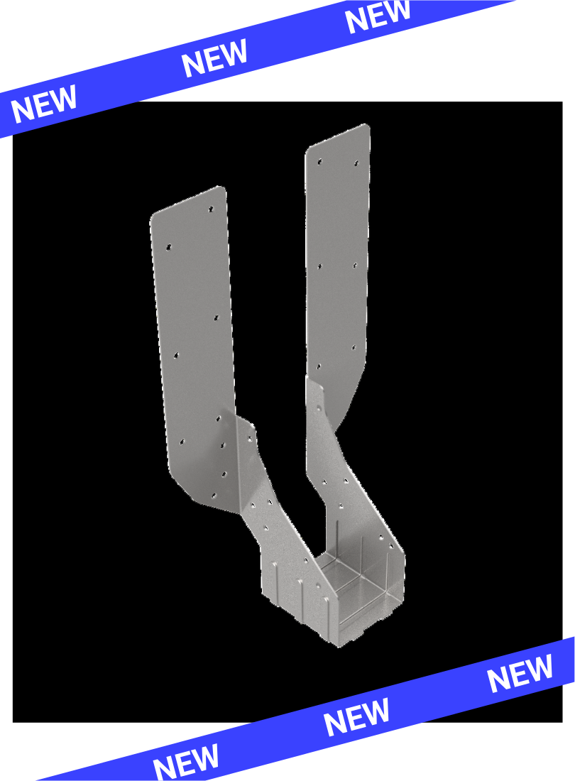
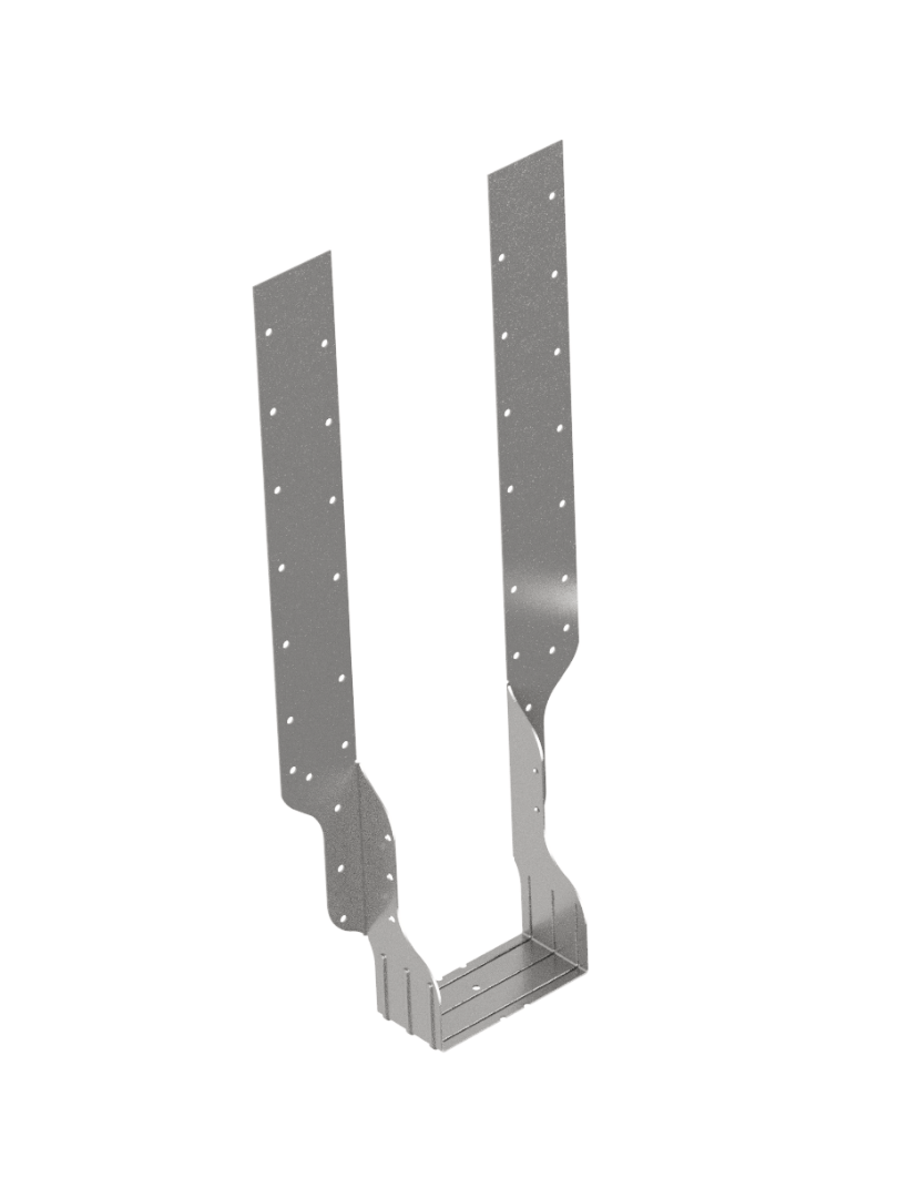
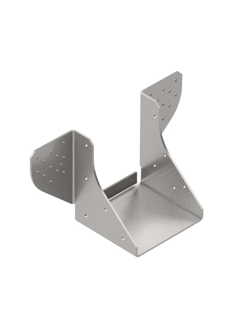
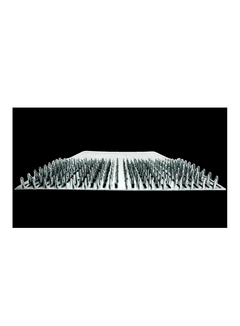
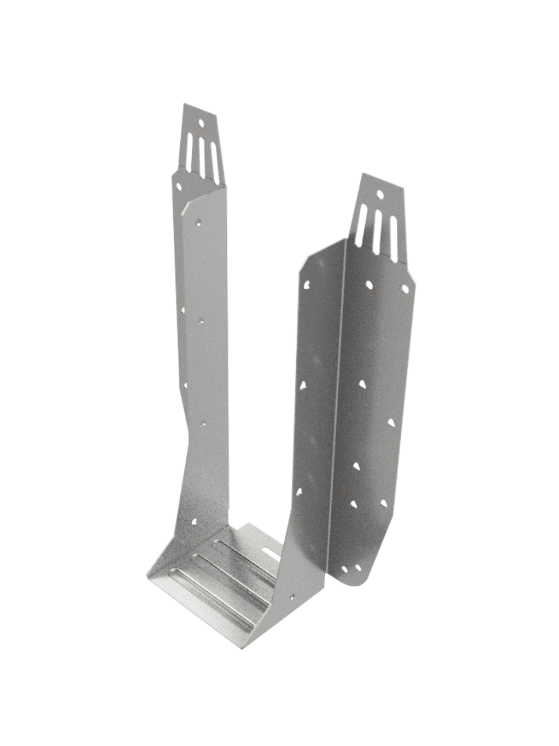
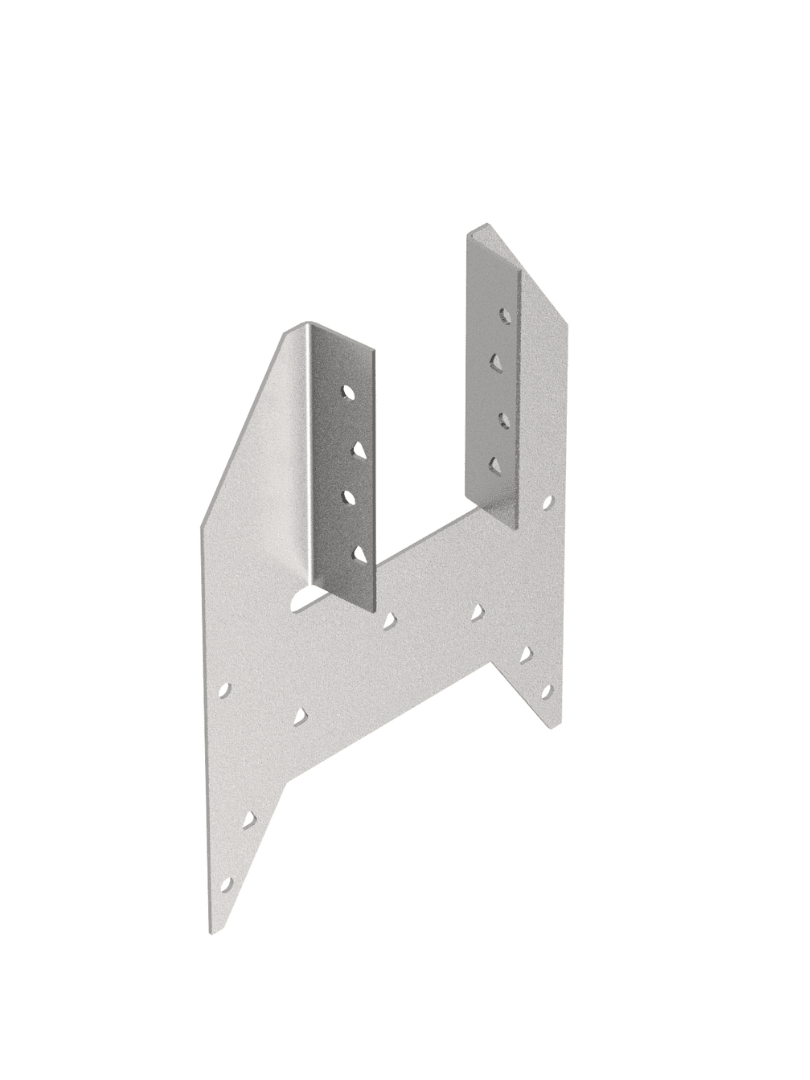
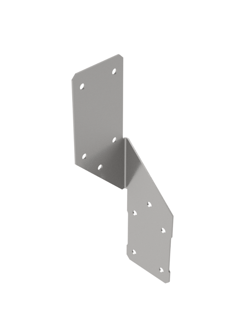
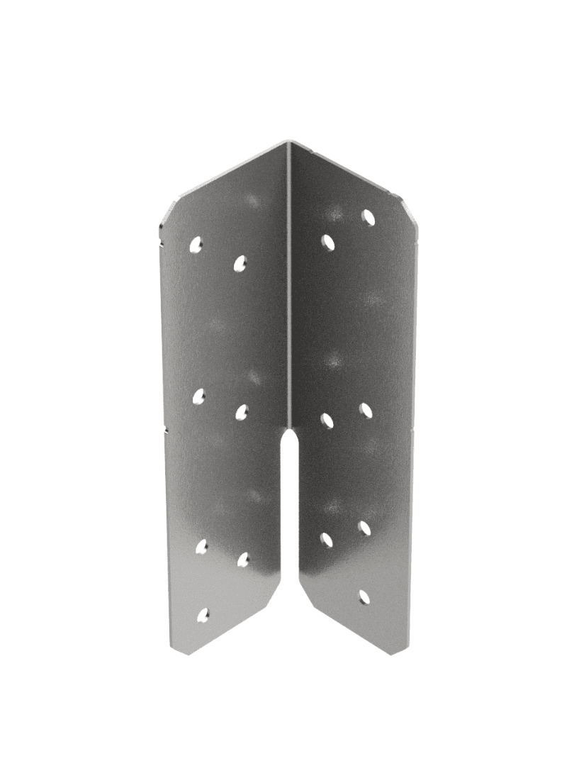
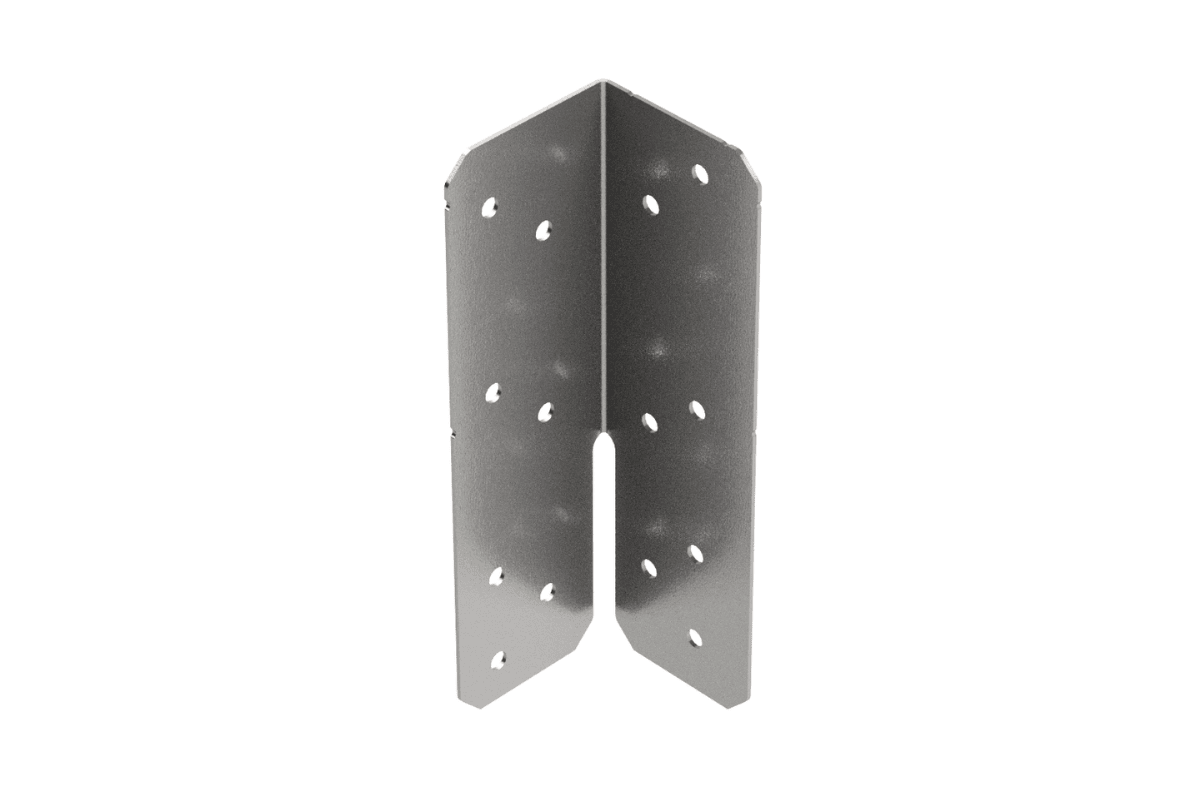
Up to 54% higher load values on standard applications
Reduction in design & on-site errors through simplification
One fixing type for all applications
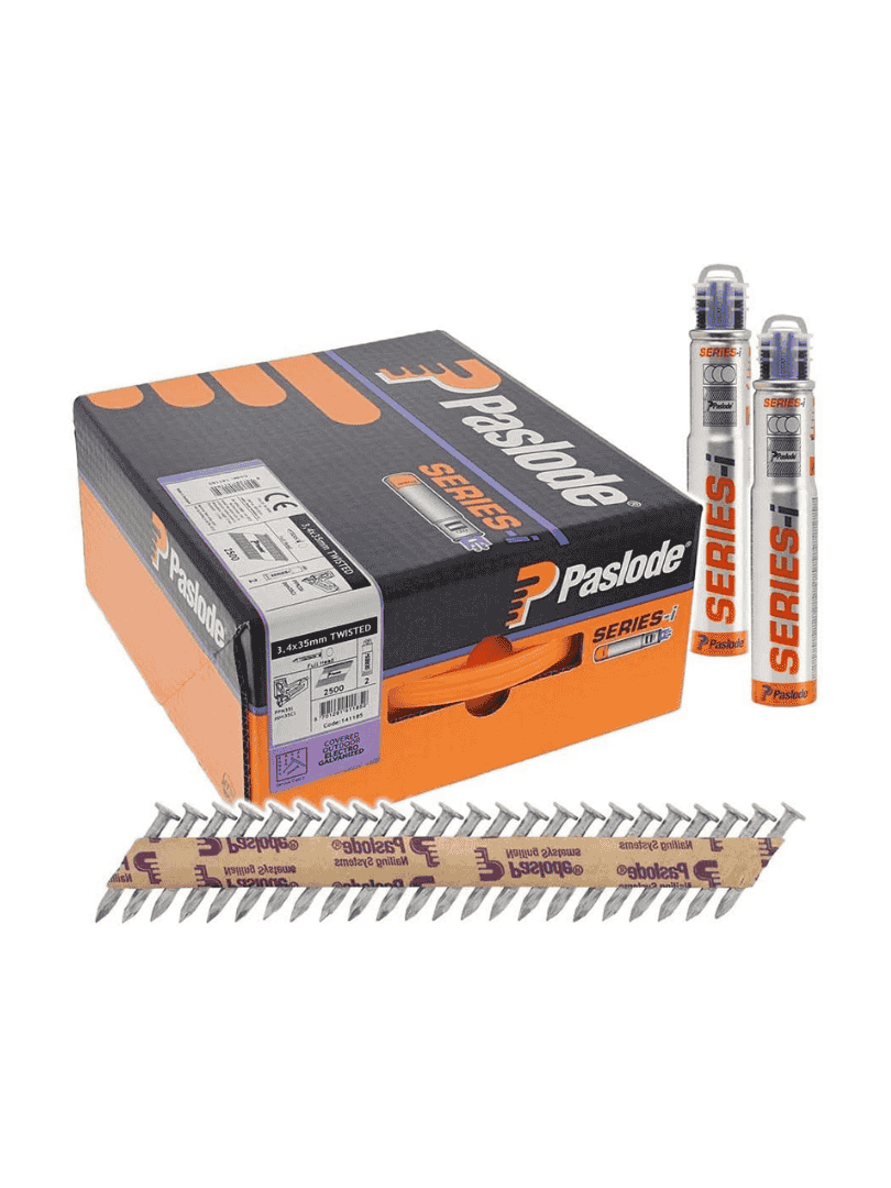
Paslode 3.4 x 35mm ElectrogalvanisedSquare Twist Nail
Cullen products have been tested and CE marked to the requirements of ETAG015 using 3.4 x 35mm square twist nails.
Masonry Fixings to be specified by the building designer.
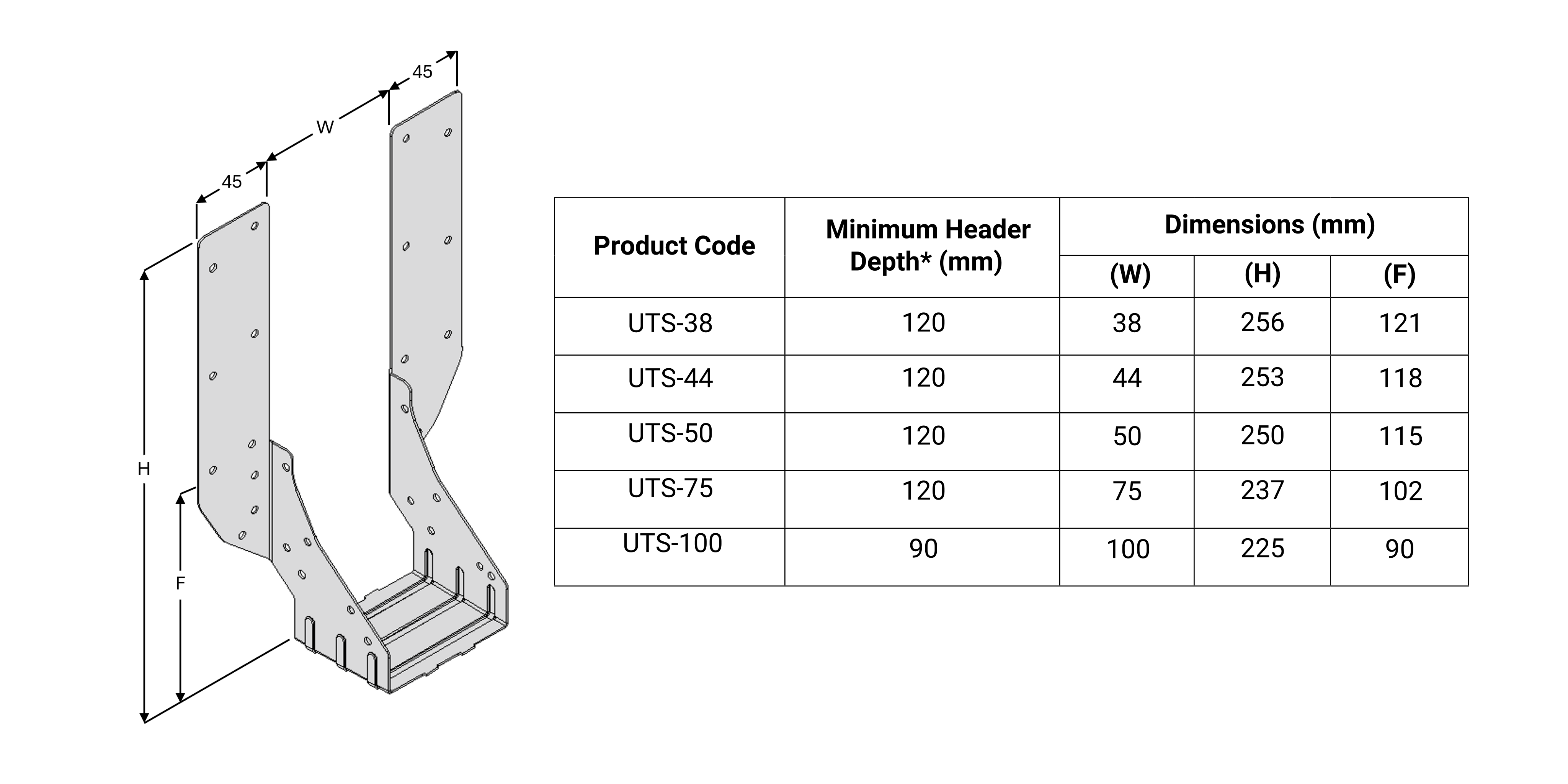
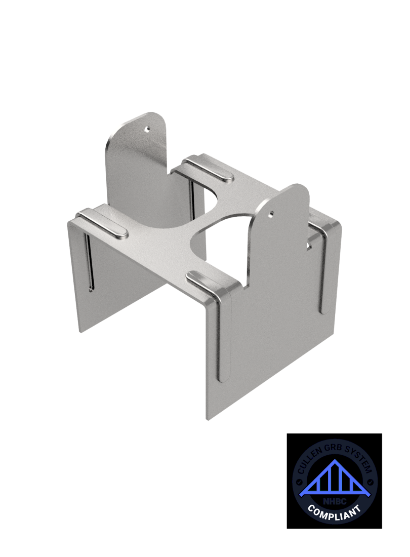
**When timber depth is shallower than ‘F’ dimension a timber packer is required.
Nail packer to truss with 3 no. fixings into front ply, 3 no. fixings into rear ply using Paslode annular ring shank 2.8 x 63mm.
Product not suitable for use with I-Joists, Open Web Joists or Solid Timber Joists (due to stirrup height "F") within a timber floor as defined by NHBC Standards Section 6.4.
When used for supporting solid timber flat roof joists, the stirrup height "F" must be a minimum of 60% of the joist depth.
Features & Benefits UTS
Explore the UTS features and benefits video
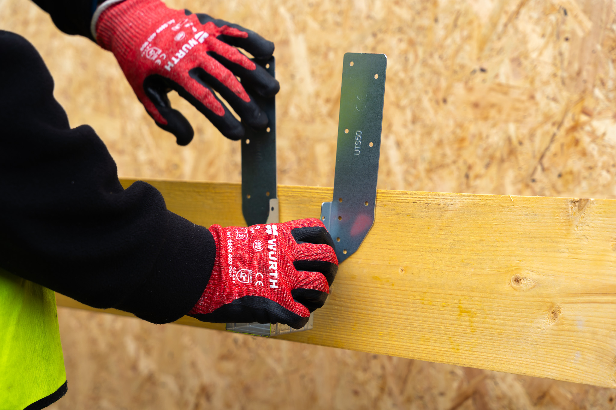
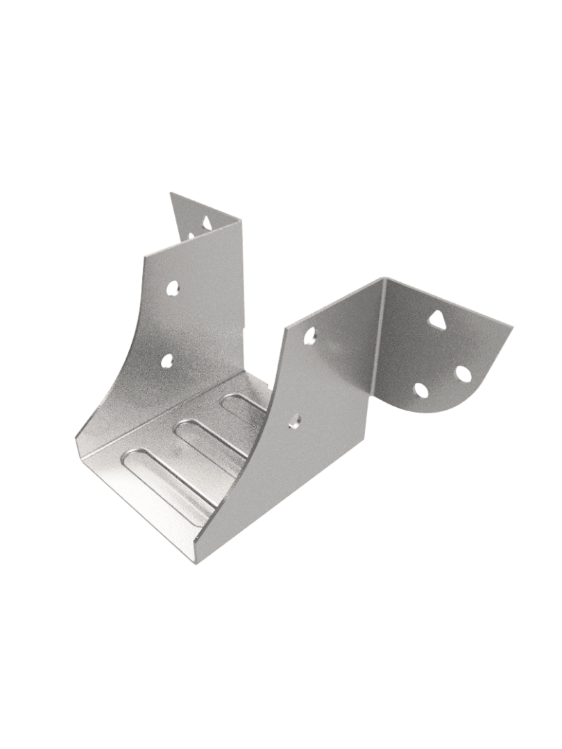
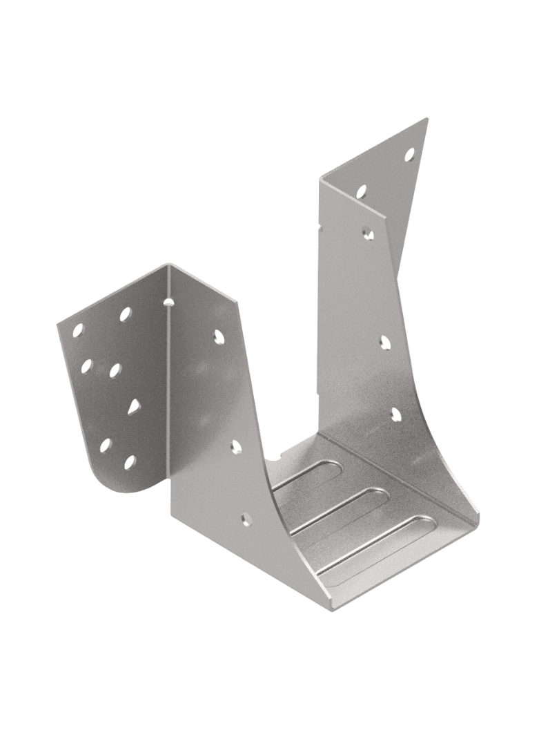
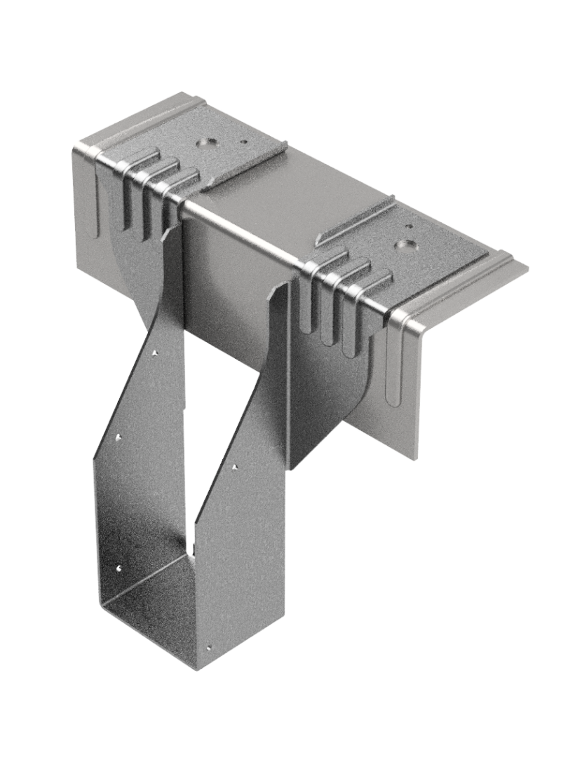
This video highlights the key features and added benefits of the Universal Truss Shoe, showcasing its versatility across five applications.
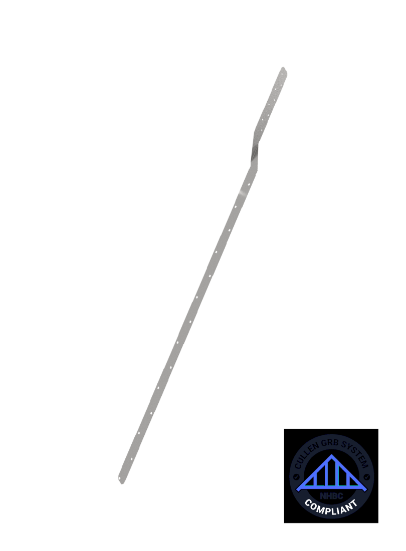
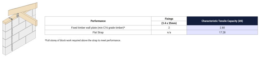
The PFS is an engineered strap that has been designed to provide enhanced performance and greater flexibility while laterally restraining floors and roofs.
Suitable for use with I-Joist, Open Web & Trusses
Engineered strap with reduced thickness and weight compared to traditional straps
One solution for floor and roof applications
Z600 or Z275
35 x 1.5mm
Galvanised Mild Steel with
Edge Protection
Up to 10.80kN
Characteristic Tensile Capacity (flat strap)
CE marking shows that a product meets EU safety and regulatory requirements.
ETA (European Technical Assessment) is a document that assesses the performance of a construction product not fully covered by a harmonised standard.
UKCA marking shows that a product meets the UK’s safety and regulatory requirements.
EPD (Environmental Product Declaration) is a verified document that reports a product’s environmental impact across its lifecycle.
View EPD
Service class defines the environmental and use conditions a construction product is designed to withstand during its intended lifetime.
NHBC (National House-Building Council) sets standards and provides warranties and inspection services for new homes in the UK.
NHBC Approved
Noggins to be installed between the I-Joists or Metal Web Joists using 2 no. UZ-Clips and 2 no. skew nails staggered either side.
After fitting all noggins the PFS strap can then be located tight to the block work and centred on the noggins.
The strap should be nailed with a minimum of 8 no. 3.4 x 35mm square twist nails evenly spaced and into at least every joist.
Only suitable when joists line through with top of blockwork
Noggins: NHBC Requirements
Width: min. ½ I-Joist depth, max. 150mm
Depth: min. 38mm
Timber: min. C16 grade
Noggins to be installed between the I-Joists or Metal Web Joists using 2 no. UZ-Clips and 2 no. skew nails staggered either side
After fitting all noggins the PFS strap can then be located tight to the block work and centred on the noggins
The strap should be nailed with a minimum of 8 no. 3.4 x 35mm square twist nails evenly spaced and into at least every joist
Only suitable when joists line through with top of blockwork
Noggins: NHBC Requirements
Width: min. ½ I-Joist depth, max. 150mm
Depth: min. 38mm
Timber: min. C16 grade
Cut a small slot in the I–Joist web, just under the top flange
Slide the PFS through the slots and position tight against the block work
To provide a fixing for the PFS, noggins must be nailed in place between the I-Joists through the I-Joist web
The strap should be nailed with a minimum of 8 no. 3.4 x 35mm square twist nails evenly spaced into the noggins
Not suitable when joists line through with top of block work
Noggins: NHBC Requirements
Width: min. 38mm
Depth: min. ½ I-Joist depth, max. 150mm
Timber: min. C16 grade
Strongback/additional noggins to be installed as per manufacturer’s guidelines
Position PFS tight to block work and centred on block
The strap should be nailed with a minimum of 8 no. 3.4 x 35mm square twist nails evenly spaced into the noggins
Roofs
Install PFS on the 25 x 100mm longitudinal truss bracing (1).
Ensure the position of the longitudinal bracing and strap coincide with the blocks vertical joint.
The 90deg bend of the strap is to be held tight against the cavity face of the inner leaf of blockwork (2), preferably located on the full block. Notch the blocks to accommodate the angle of the strap and ensure notch is fully mortared.
Install PFS on the 25 x 100mm longitudinal truss bracing (1).
Ensure the position of the longitudinal bracing and strap coincide with a horizontal blockwork joint.
The 90deg bend of the strap is to be held tight against the cavity face of the inner leaf of blockwork (2), preferably located on a substantial piece of blockwork, i.e. over the centre of a full block, with a single cut block over the strap (3). Notch the blocks to accommodate the angle of the strap and ensure notch is fully mortared.
Ensure the position of the straps coincides with the horizontal blockwork joint.
Install PFS to underside of solid noggins (1). Noggins to be fixed horizontally to avoid twisting of the restraint straps.
The 90deg bend of the strap is to be held tight against the cavity face of the inner leaf of blockwork (2), preferably located on a substantial piece of blockwork, i.e. over the centre of a full block, with a single cut block over the strap (3). Notch the blocks to accommodate the angle of the strap and ensure notch is fully mortared.
Fix straps to noggins/trusses with 8 no. 3.4 x 35mm square twist nails, evenly spaced along the length of the strap. Ensure a minimum of 2 fixings into noggin beyond the 3rd rafter (4).
Install PFS on the 25 x 100mm longitudinal truss bracing (1). Bracing to be fixed to each truss with 2 no. 3.35 x 65mm round wire nails.
Ensure the position of the longitudinal bracing and strap coincide with a horizontal blockwork joint, where this is not possible inserted a cut block to suit strap location (4).
The 90deg bend of the strap is to be held tight against the cavity face of the inner leaf of blockwork (2), preferably located on a substantial piece of blockwork, i.e. over the centre of a full block.
Guidance
Straps to be installed at not more than 2m centres (or 1.25m where appropriate) along gable end
Strap to be of sufficient length to be fixed to a minimum of 3 no. trusses
Blockwork to be built up to suit strap location
Longitudinal bracing to be fixed to each truss with 2no. 3.35 x 65mm round wire nails (in all details 3.1 x 90mm long mechanically driven nails may be substituted for 3.35 x 65mm long wire nails)
Where the position of the strap does not coincide with an existing longitudinal truss brace, then the strap may be fixed to an additional 25 x 100mm longitudinal binder (as shown in following details). The binder to be fixed over a minimum of four trusses and fixed to each truss with 2no. 3.35 x 65mm round wire nails.
Fix straps to longitudinal bracing with 8no. 3.4 x 35mm square twist nails, evenly spaced along the length of the strap (for NHBC warrantied buildings, in accordance with NHBC Standards 2017 section 7.2.8, 8 no. 25 x 4mm steel screws shall be used instead of square twist nails)
Parallel restraint straps are not required to roof trusses unless specified by building designer
These have been issued as guidance only, the overall responsibility lies with the Building Designer. For 3rd floor and above please refer to the building standards or building designer for guidance. All straps require a full storey of block work above to achieve the full 8kN declared load capacity.
Gable Restraint System
Cullen PFS restraint straps fixed to solid timber noggins between trusses at maximum 2000mm centres with 3.4 x 35mm square twist nails, 8 no. to noggins and 4 no. to gable panel (2 no. top face & 2 no. cavity face)
Installation Guidance
Explore the step-by-step PFS installation video
The video demonstrates best practice on site, highlighting each stage of the installation process to help ensure accuracy, consistency, and compliance during fitting.
Fixings into masonry to be specified by building designer.
Installation Guidance
Explore the step-by-step VRS installation video
The video demonstrates best practice on site, highlighting each stage of the installation process to help ensure accuracy, consistency, and compliance during fitting.
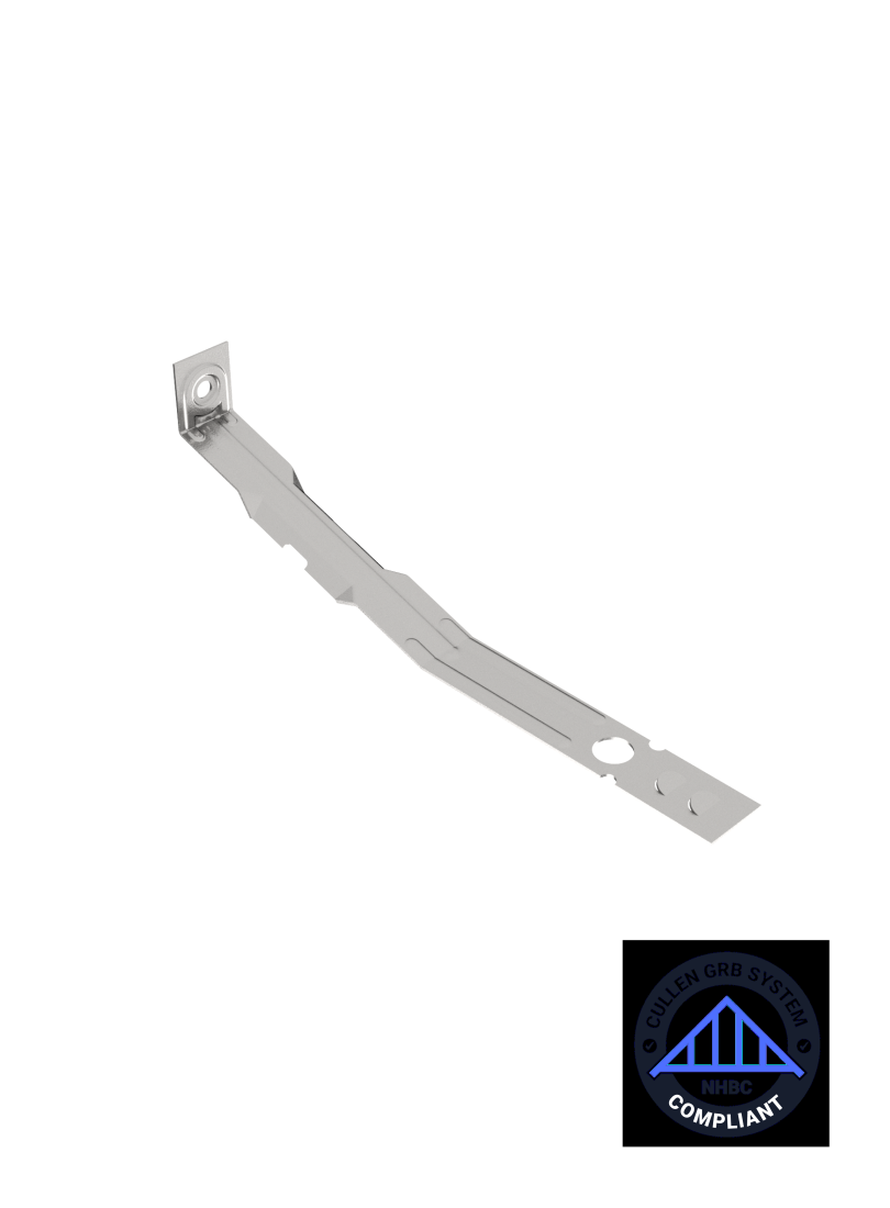
Cullen RST-3 restraint straps at maximum 1200mm centre fixed to longitudinal truss bracing / additional longitudinal bracing with 8 no. 4 x 25mm steel screws fixed to gable panel stud with 3 no. 3.4 x 35 mm square twist nails.
Twisted Strap To Truss
RST strap to be nailed to truss with 3.4 x 35mm square twist nails. Nail quantity dependant on uplift value. Fixings into masonry to be specified by building designer.
Nail quantity dependant on uplift value.
Fixings into masonry to be specified by building designer.
Installation Guidance
Explore the step-by-step RST installation video
The video demonstrates best practice on site, highlighting each stage of the installation process to help ensure accuracy, consistency, and compliance during fitting.
The GRB is an engineered bracket that has been designed to provide a verified connection between a timber gable and masonry wall when used in conjunction with the Cullen Gable Restraint System*.
Following the details from the system means no external engineering checks
Safely transfers the loads into the roof diaphragm
Z600
Galvanised Mild Steel
EPD (Environmental Product Declaration) is a verified document that reports a product’s environmental impact across its lifecycle.
View EPD
Service class defines the environmental and use conditions a construction product is designed to withstand during its intended lifetime.
NHBC (National House-Building Council) sets standards and provides warranties and inspection services for new homes in the UK.
NHBC Approved
The video demonstrates best practice on site, highlighting each stage of the installation process to help ensure accuracy, consistency, and compliance during fitting.
Single anchor means the part is not width dependant
Paslode 3.4 x 35mm ElectrogalvanisedSquare Twist Nail
Cullen products have been tested and CE marked to the requirements of ETAG015 using 3.4 x 35mm square twist nails.
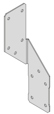
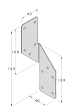
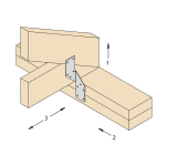
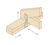
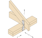
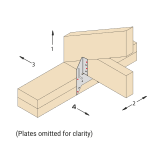
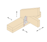
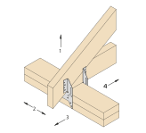
1 no. TA–1 standard installation**
1 no. TA–1 installed to opposite side**
1 no. TA–1 installed to outer face**
All hangers in this range do not provide restraint, therefore restraint straps may be required for joist applications
Floor can be propped with acroprops and fully decked but must not be fully loaded until the masonry above has fully cured
Double wall plate required for all installations (min. 75mm) unless using in a timber frame application where theframing anchor can be fitted to the head binder.
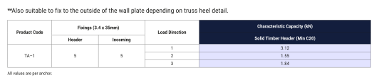
Also suitable to fix to the outside of the wall plate depending on truss heel detail.
Eliminates damage from skew nailing into the wall plate
“Push on” fit allows truss anchor to be retained in position prior to nailing
Optional triangular nail holes for enhanced performance
Eliminates the need for a pre-cut angle barer to support the valley truss or pre-cut angle to valley truss
Paslode 3.4 x 35mm ElectrogalvanisedSquare Twist Nail
Cullen products have been tested and CE marked to the requirements of ETAG015 using 3.4 x 35mm square twist nails.
Truss to Wallplate
Standard Installation
Double wall plate required for all installations (min. 75mm) unless using in a timber frame application where the framing anchor can be fitted to the head binder.
Enhanced Installation
Double wall plate required for all installations (min. 75mm) unless using in a timber frame application where the framing anchor can be fitted to the head binder.
2 no. Truss Anchors
Double wall plate required for all installations (min. 75mm) unless using in a timber frame application where the framing anchor can be fitted to the head binder.
Valley Truss
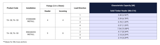
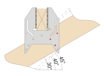
The TA can be used in conditions where the supporting truss is a maximum 45° slope. Fill the 3 nail holes highlighted above to the supporting truss (dependant on TA orientation) and fill 4 no. nail holes (2 no. each face) for the incoming truss for correct installation.
Double wall plate required for all installations (min. 75mm) unless using in a timber frame application where the framing anchor can be fitted to the head binder
The TA can be used in conditions where the supporting truss is a maximum 45° slope. Fill the 3 nail holes highlighted above to the supporting truss (dependant on TA orientation) and fill 4 no. nail holes (2 no. each face) for the incoming truss for correct installation

 Floors
 Roofs
Roofs Walls
Walls Fixings